One battery, three phases: designing the Tepla Gora microgrid
Why a building with a 25 kW peak gets a 19 kW inverter group, and why a three-phase site runs entirely on single-phase equipment
The PV article ended with a wish and a question. The wish was 60 kWh of battery. The question was how much inverter a building like Unity Hub actually needs. Both got answered over the summer, and neither answer is the one we expected in March.
The building's electrical load table adds up to about 25.8 kW at full coincidence. The obvious reading is a 25 kW three-phase hybrid inverter with a high-voltage battery behind it: one box, one cable, done. The site instead gets a group of three single-phase inverters of 8 kW each, 19.2 kW in total, and a 48 V battery of about 47 kWh. This article explains why the smaller number is the right one, what runs on it, and what happens when the grid goes away.
The feed is not the inverter
The first thing to separate is the building's peak from the inverter's job. The peak is a requirement on the grid connection and the main board. Sauna, event kitchen, heat pump, lift, all on at once: that current comes in from the street and goes through the main distribution board. It never needs to pass through an inverter.
The inverter is sized for something else: what lives on the battery every day and in a blackout. That set is much smaller. Home automation and IT, lighting, ventilation, circulation pumps, fan coils, baseline sockets. Add the non-critical group that we decided to keep on the island (more on that below), and the honest number is 10 to 14 kW. Sizing the inverter to 25 kW would pay for capacity that the battery could feed for about two hours anyway.
Then why three units? Because a three-phase connection is not one large channel. It is three separate lines of roughly 10 kW each, about 50 A per phase. The building's circuits get spread over three phases whether we like it or not, and the sun has to reach all of them. A single-phase inverter on one phase would leave two thirds of the consumers without solar. So the group stands on all three phases, one unit per phase, while the equipment itself is single-phase throughout. There is not one three-phase appliance in the design. The three phases come from how the site connects to the grid, not from what the equipment needs.
A star with one centre
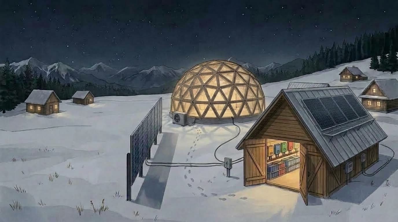
The architecture is a DC-centric star. Every roof on the site feeds a charge controller. Every charge controller feeds one 48 V battery. One inverter group takes power from that battery and forms the island's AC network. All of this lives in TeploHub, the technical building that went up beside the workshop this year.
Microgrid scheme, architecture v4.3, July 2026: roofs as sources, the electrical heart in TeploHub, the island sub-board, the main board with the grid boundary, and the three operating modes.
Near roofs, the workshop and TeploHub roof, come in as strings of about 250 V, which is where the four-panels-per-string rule from the PV article comes from. Tiny houses, when they arrive, each bring a string of about 400 V to TeploHub: higher voltage survives the distance, and the DC pair rides in the same trench as the house's AC line. A charge controller rated for 450 V takes eight or nine panels per string and halves the number of cable pairs. An empty tiny house is a pure donor; a full one draws from the commons without billing, with current monitoring and winter rules in the automation.
Charging is one conversion, DC to DC, past the inverters. That is why the group is sized from AC consumption and not from the size of the solar field. More panels mean more charge controllers on the same bus, not a bigger inverter. Growth from 20 kWp to 30 kWp changes nothing on the AC side.
Physically: charge controllers, battery, inverter group, the island sub-board and the main board sit in TeploHub. The heat pump, its buffer and the floor boards sit in Unity Hub. Two power lines run between the buildings, one main and one reserve, in the same trench as the heating pipes.
What runs where
The site has two lanes.
The island is what the inverter group forms on its first AC output. The core of Unity Hub is there: everything that runs around the clock. In July we moved the non-critical group there too, permanently: sauna at about 3 kW, event kitchen with induction at 4 to 7 kW, and two single-phase EV charge points of 7.4 kW on different phases. When the grid is live, that group is fed through the inverters' transfer relay; conversion covers only the difference, so island wiring does not change the 19.2 kW argument. When the grid is dead, the group does not go dark by design. It falls down a ladder of load shedding, by state of charge, within the island's ceiling.
The grid lane is the main board. It carries the heat pump in winter and a future lift, if one is ever installed. The heat pump has three routes for its energy. On a cloudy winter day it draws from the grid directly, batteries out of the path. On a sunny winter day the inverter group pushes solar surplus back into the main board's bus, and the meter at the boundary sees only the difference. That is not a smart function of the inverter; it is Kirchhoff's law on a busbar. In a blackout an automatic transfer switch in the main board moves the heat pump's feed onto the island. Its compressor at about 3.4 kW fits inside one phase; the 3 kW electric backup element is shed.
Keeping the heat pump on the grid lane in normal operation has two reasons. Winter heat is 20 to 60 kWh a day for two or three months. Running that through the battery would add a 10 to 15 percent round-trip loss and half a cycle to a full cycle of battery wear every day, for nothing. The daily shift for heating is done by the thermal battery instead, the 300 L buffer and the mass of the CLT and screed. The second reason is the line, and the line deserves its own section.
Why not one 25 kW hybrid
We compared the star against a single 25 kW three-phase hybrid with a high-voltage battery. It is a legitimate machine for a different architecture, one where the entire feed passes through the inverter, which is exactly why it needs 25 kW.
The star wins on four counts. Battery: a 48 V bank can be assembled from prismatic cells at roughly half the cost per kilowatt-hour of a matched high-voltage rack, and it is the chemistry we already run at House 001. Solar scaling: a charge controller per roof, without limit, against two trackers on the hybrid, which caps out at about four roofs. Failure: one dead unit in a group of three degrades the site; one dead hybrid darkens it. Integration: the group's gateway speaks natively to the home automation server, without a vendor cloud in the loop.
The hybrid's honest advantages: a higher peak efficiency, a whole-building uninterruptible supply, one box, and a cheaper inverter per kilowatt. The whole-building UPS is worth less than it sounds. Forty-seven kilowatt-hours divided by a 22 kW peak is about two hours. With the battery included, the two options landed at roughly the same cost after we upsized the group from 5 kW to 8 kW units in July. The decision holds on the battery, the scaling and the failure mode, not on price.
The upsizing itself was a budget argument, not a technical one. The inverter group is the one non-granular component in the system. Panels, cells and charge controllers can be added later in small steps with whatever money is around. The group cannot, so it was sized for the site's eventual life, with a path to a second three at a later date.
The battery
The plan is 47 kWh of lithium iron phosphate at 48 V: the community's existing self-built 15 kWh pack plus a new 32 kWh pack from sixteen prismatic cells assembled on site. That is the same construction House 001 has run for years. It is below the 60 kWh the PV article wished for, and it is enough, for a reason that took us a while to see.
The battery does not need to carry winter heat. The grid lane does that, and the thermal mass does the daily shift. What the battery carries is the island at night: the core and whatever the shedding ladder allows. A sauna session is about 9 kWh, a fifth of the bank. Whether the sauna runs on a winter evening in a blackout is a question about energy in the bank, not about whether the sauna is "critical". That is also why we left the inverters' second AC output unused. That output is designed to go dark the moment the grid disappears. Our shedding criterion is available energy, from state of charge, sun and forecast, and an output that cannot express "grid is dead, but the sun is out, keep going" is the wrong tool. A summer blackout at Tepla Gora should look like an ordinary summer day.
Two worlds
The line quality decides more than the inverter does.
The site turned out to have two grid feeds, not one: a single-phase line to the cafe and hostel, and a three-phase line to the workshop. On paper the three-phase line is good for 64 A, about 44 kW, more than the 30 kW we intend to request. In practice, charging one electric car at 2.5 kW drops the voltage to 160 V against a norm of 230 V plus or minus 10 percent. Somewhere upstream there are about 5 ohms of impedance. Paper is not copper.
So the design has a fork. In world A the operator fixes the line, which is their normative duty. The grid input of the inverter group is active, the heat pump runs on the grid in winter, surplus flows out and the annual balance is honest. In world B the line stays sick. Then the grid enters the site only as a battery charger, either through telecom-class 48 V rectifiers with a wide input window, the House 001 pattern, or as a trickle through the group's grid input with a current limit. The heat pump then draws from the island through the transfer switch, the boiler takes a larger share of winter, and the price is a round-trip loss. Export into 5 ohms is pointless in either world: the voltage rises and the inverter trips.
The island is identical in both worlds. Only a few positions in the main board differ. Which world we live in is decided by two measurements, not by opinion: which feed the charge point sits on, and a load step at the first accessible point after the sealed meter, voltage without load against voltage under a known 2 kW, which gives the upstream impedance.
Shedding, bypass, and the cost of always-on
Load shedding has two layers. The home automation server is the upper one, with schedules and solar forecasts. Under it sits a hardware fallback that needs no server: a relay in the inverter group's gateway, driven by state of charge, controls the same contactors and drops the optional groups when the bank falls below a threshold. This closes the corner case "blackout plus a dead server", where comfort-first contactors would quietly drain the battery. The EV charge points carry their own solar-surplus logic and follow it with or without the grid.
Each tiny house gets the same panel: a critical group wired directly, fridge, light, router, and an optional group behind a normally-closed contactor under automation. A deficit sheds optional groups, never whole houses.
The main board also gets a manual bypass, a 1-0-2 changeover that feeds the island sub-board straight from the grid bus with the inverter group fully isolated. It exists for service: a firmware update takes the whole group down for ten to twenty minutes, and in a three-phase group one dead unit stops all three. It also lets the building live on the bypass before the inverters are even installed. The transfer switch and the bypass are different devices with different philosophies, one automatic per load, one manual for service, and we deliberately did not merge them.
Always-on has a price. Three units idle at about 29 W each, about 87 W together, which is about 0.76 MWh a year, or about 0.5 MWh in the group's sleep mode. That number was checked against the datasheet and accepted. It is the cost of a site that does not go dark.
What is open
The inverter group is approved by the team and not bought; purchase is likely in 2027. The gateway model and the failure modes of the contactors are still to be specified. The battery has not moved. The first ten or so panels are likely to go onto the new metal roof over the workshop and TeploHub within weeks, which gives the first charge controller something to do. The utility request, the line diagnosis and a voltage-quality measurement are ahead. Expansion to six units is possible on paper and brings a requirement of its own: two units on one phase must be paralleled through an external transfer switch, which belongs in the budget of that future step.
The star is drawn. What it costs to run through a Carpathian winter, in kilowatt-hours and in comfort, is a measurement for 2027.
This investigation is part of the Unity Hub energy system design within the UA Unity Hub project at Tepla Gora. Related: Designing a winter-optimized PV system for a Carpathian eco-community, What kept changing our mind about heating a Carpathian eco-community.
Article Details
- Published
- September 26, 2026
- Related Project
- UA Unity Hub